CellDesigner 3.0
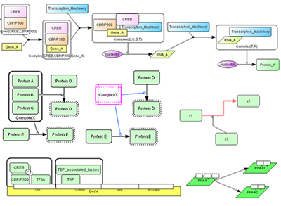
 CellDesigner 3.0 implements a new graphical notation that enhanced previous process diagram into gene and RNA, as well as protein complex structures.
 New Graphical Notations
Version 3.0 implements most part of notations described in Kitano, et al., "Using process diagram for the graphical representation of biological networks," Nature Biotechnology, August 2005.
Samples:
*The examples in the above paper are included as the sample files and many more.
Note: For those who have been using CellDesigner 2.X
The function to create or to release heteromultimers has been replaced by more general form of complex formation.
By "complex" you will get boundary of the complex and you can either put
proteins or take out protein. (See the middle section of the example on the right)
Edit and Layout functions Enhancements
- You can use Right click menu on Species/Compartment/Reactions which list up all the available operations on the target component.
- Reactions can be drawn to and from 16 connection points around the component.
- Reaction can be drawn in polyline and orthogonal.
- You can add / remove anchor points of the reaction.
- Alignments icons are available on the tool bar. Select any number of components and align them as you like.
- Fine position adjustment can be done by Up/Down/Right/Left keys.
- Select all the items in the model.
Running Simulation with Control Panel
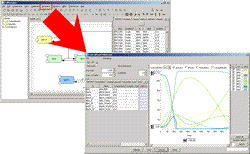
 The “Control Panel”, introduced in CellDesigner Version 2.5, is designed to assist the users to simulate directly from CellDesigner controlling the amounts and parameters of the Species.
Calling SBML ODE Solver directly from CellDesigner, ControlPanel enables you to specify the details of parameters, changing amount, conducting parameter search, and interactive simulation with intuitive manner.
See also: "Running Simulation with Control Panel" (PDF version)
 New Graphical Notations

 The “
The “