Operators
The following operators are available for CellDesigner Block Diagram Editor.
| and | Output the product of the inputs. If all the product is non-zero, output "1", otherwise output "0". |
| or | Output the sum of the inputs. If the result is non-zero, output "1", otherwise output "0". |
| add | Output the sum of the inputs. |
| multiply | Output the product of the inputs. |
| threshold | Specify the condition of the inputs. The value can be specified when placing the icon. Specify the integer value more than zero after one of the following symbols ">=", ">", "<=", or "<". e.g. If you want to output the value more than 1.5, specify ">=1.5" here. AutoActivation |
| auto activation | Always output "1" despite the value of the inputs. |
| assign | Always output the specified value. The value can be specified when placing the icon. |
By double clicking the operator, you can specify the output value.
All the operators output the result of the input processing, when the results is non-zero, CellDesigner outputs the pre-specified value, when the results is zero, output value zero.
Routing
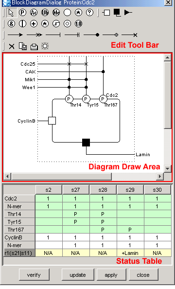
You can connect the routing inside the block freely.
"Activation" and "Absolute Activation" convey the output from the operators directly.
"Inhibition" and "Absolute Inhibition" output the value "0" if the output from the operators is non-zero, otherwise "1" if the operators output is "0".
The routing for activity of the residue can be added by clicking the line drawn from the residue, then clicking on the left side of the block area.
If same external protein activates or inactivates the residue, click the line from the residue, then click on the external protein name.
Change Name and Value
- Double-click on the name to change the name of the residue and external protein.
- The value of the operators can be changed by double-clicking the value.
Verify the status
- Press "Verify" button, then CellDesigner verifies the diagram drawn with the routing and operators against the regulation data from the process diagram.
- If there is any conflict between the block diagram and the process diagram depicted, the background of the "activity" cells in the table will be displayed in red.
- If there is possibility of the conflict, the background color will be in light red.
- The cells with no color changes indicate there is no discrepancy.
Retrieve the up-to-date process diagram data
- Press "update" to update the block diagram with the data from the up-to-date process diagram.
Fix the changes
- Press "apply" button to fix and apply the data edited by the block diagram dialog.
Close the dialog
- 1. Press "close" button to close the dialog.
- If there is any change in the diagram, the message is prompted if you apply the changes.
Re-open the block diagram after editing the process diagram.
When re-open the block diagram after editing the process diagram, newly added residue, BindingSite, EffectSite, and Degradation are automatically added if necessary.
If the residue, BindingSite, EffectSite, or Degradation already placed in the block diagram is deleted from the process diagram, such item will not be deleted automatically. You should delete them manually from the block diagram.
