

[ Table of Contents ]
- 0 Introduction
- 1 Installation and Startup
- 2 Quick Tutorial of Model Building
- 2.1 Open a File
- 2.2 Select an Item
- 2.3 Move / Delete an Item
- 2.4 Compartment
- 2.5 Undo / Redo
- 2.6 Change the size of an item
- 2.7 Species and Reactions
- 2.8 Change the Shape of Compartments
- 2.9 Activate a Species
- 2.10 Create New Species, Reactions, and Compartment
- 2.11 Add Notes to the Components
- 2.12 Export Image
- 2.13 Export List to CSV file
CellDesigner 2.0 New Features:
CellDesigner 2.0 now supports the following features:
- Intuitive User Interface
- Display in color (Species and Compartments)
- Support Block Diagram (*Proto-type)
- Extract the control relationship between Proteins from the pathway diagram.
- Describe and Verify the Modifications/Activations Logic.
- Extensive Notes Description (to Compartment, Species, Reaction, Protein)
- Support New Symbols
- Relationship between elements: unknown catalysis, unknown inhibition.
- Residue Modification: Hydroxylated
- SBML Compliant (Level 2 Version 1)
- Output Lists to CSV format.
- Output Images in PNG format.
CellDesignerTM's features:
- Biochemical, Gene Regulatory Networks Modeling with GUI
- Visual Representation of Biochemical Semantics
- Detailed Description of State Transition of Protein
- SBML (=Systems Biology Markup Language) Compliant
- Linkage to SBW Powered Simulator Modules
- Extreme Portability as a JAVA Application
CellDesigner 2.1 New Features:
On top of the following CellDesigner 2.0 features, CellDesigner 2.1 now supports:
- SBW 2.0 support
- Other Enhancements
- Bug fix
1.1 Operating Environment
The current version of CellDesigner requires Java2 Runtime Environment (JRE1.4.2 or later) on Windows (95 or later), MacOSX (10.3 or later), and Linux with X Window System. On MacOSX, Java 1.4.2_05 or later is required.
On Linux platform, running under twm and windowmaker window managers is recommended; some problems will arise if you use window environments other than these.
If SBW and its modules have already been installed, these modules are available. Especially time evolving simulation of editing models can be performed.
1.2 Install SBW and SBW Modules
If you are interested in time evolving simulation and analysis on biochemical networks, we recommend you to install the Systems Biology Workbench (SBW) and SBW-powered software before you install CellDesigner.(*)
Please check http://www.sbw-sbml.org/index.html and download the software from Software/Download section.
To install SBW and SBW-powered software, follow their installation instructions.
If you would like to use CellDesigner alone right now, you can postpone this step until you need simulation and/or analysis.
Note: SBW Linux version
As for CellDesigner Linux version, its installer can detect the SBW library which has been installed into the default path prompted by the SBW installer. The default path of SBW is the user home directory ($HOME/SBW/lib) . If you change the default path of SBW, make sure you set the right path when you install CellDesigner.
- (*) SBW 2.0 is available on Windows. SBW 1.0.5 is available on Linux. For details on SBW 2.0 information: http://sys-bio.org/research/sbwIntro.htm.
- (*) Caution (Dec 2004)CellDesigner 2.0 was originally developed with SBW 1.0.5.
We are currently testing CellDesigner against newly released SBW 2.0, and preparing CellDesigner 2.1, which will be available soon.
In the meantime, follow the instruction for the setup "connecting SBW 2.0 and CellDesigner 2.0"
1.3 Install CellDesigner
The current release is distributed in archived installer package for each operating system.
- Windows: CDInstall_2_1_1_win.exe, Setup_SBW_1_modules.exe (*)
- MacOSX: CDInstall_2_1_1_mac.zip
- Linux: CDInstall_2_1_1_linux.bin
- (*) Setup_SBW_1_modules.exe is to setup the SBW modules that CellDesigner uses.
While J2RE is required for CellDesigner to run, the installers for Windows and Linux include it, and MacOSX has a Java runtime environment initially. Therefore, you do not need to download or install J2RE. (If you installed SBW, you have already had it anyway.) Download the one for your operating system and follow instructions below to install CellDesigner for each environment.
Windows:
- Double click CDInstall_2_1_1_win.exe.
The installer window should open, and follow the message therein. - Select the install set according to your choice of SBW.
- *For those who have installed SBW 2.0,
when the message “Start SBW 2.0 Broker” is displayed,
Start “C++ Broker” by selecting Windows’ [Start] menu then – [Systems Biology Workbench] – [C++ Broker].
- Press [Next] to execute the rest of the installation.
- When completing the installation of CellDesigner, start SBW_1_modules.exe to install the SBW simulation modules.
Note: In case you have installed SBW 2.0 and you encounter an error while installing CellDesigner, there might be a possibility that the C++ Broker is up which prevents CellDesigner to start. Please try to kill the broker using the Task Manager, or restart your system before you resume the CellDesigner installation.
MacOSX:
- Double click CDInstall_2_1_1_mac.zip.
- The compressed installer should be recognized by Stuffit Expander and should automatically be expanded to CDIinstall_2_1_1. Then double click it.
The installer window should open, and follow the message therein.
Linux:
- Open a shell and, cd to the directory where you downloaded the installer.
- At the prompt type: sh ./CDInstall_2_1_1_linux.bin.
The installer window should open, and follow the message therein. - If you have installed SBW,
- Select the install set according to your choice of SBW.
- Set the path to the SBW library.
[Installed File Images]
After installation finished, you would see the following directories/files in the installation directory (CellDesigner2.1.1 by default).
+00README.txt
|
+CellDesigner2.1.1 executable application module(*for Mac: CellDesigner)
+CellDesigner_register_to_SBW
|
+documents/
| +startup_guide21.pdfthis document
|
+exec/
| +celldesigner.jar library for CellDesigner application
|
+jre (1.4.2_06) *(Windows, Linux only)
|
+lib
| +sbw/
| +SBWCore.jar
| +browserlauncher/
| +browserlauncher.jarlibrary web browser launcher by Eric Albert
| +mrjadapter/
| +MRJAdapter.jarlibrary for MacOSX feature by Steve Roy, Software Design
| +xerces/
| +xercesImpl.jar XML library by the Apache Software Foundation
| +xml-apis.jarXML-API library by the Apache Software Foundation
|
+licenses/
| +mrjadapter/
| +lgpl.txt
| +xerces/
| +LICENCE
| +LICENCE-DOM.html
| +LICENCE-SAX.html
|
+samples/
| +components.xml sample for various components
| +M-Phase.xml sample for model editing
| +M-Phase2.xml sample for model editing
| +simulation.xmlsample for simulation
| +test-level1.xmlsample for SBML level 1 document
| +test-level2.xmlsample for SBML level 2 document
|
+Uninstall_CellDesigneruninstaller module directory
SBW_1_modules (installed by Setup_SBW_1_modules.exe)
+jre (1.3.1_11)
|
+licenses
| +lgpl.txt
|
+modules
| +plot.jar
| +SimDriver.jar
|
+Uninstall_SBW_1_modules
1.4 Startup CellDesigner
Windows:
- Double click shortcut icon
 CellDesigner2.1.1 in your desktop.
Or double click CellDesigner2.1.exe in the directory where you chose to install (C:\Program Files\CellDesigner2.1.1 by default).
MacOSX:
- Click icon for CellDesigner in dock.
Or double click CellDesigner in the folder you chose to install (Application/CellDesigner2.1.1 in you home directory by default).
Linux:
- On a shell, cd to the directory where you chose to create links and type ./runCellDesigner2.1.1.
Or type ./runCellDesigner2.1.1 after cd to the directory where you chose to install (CellDesigner in you home directory by default).
1.5 CellDesigner Screen and Navigation
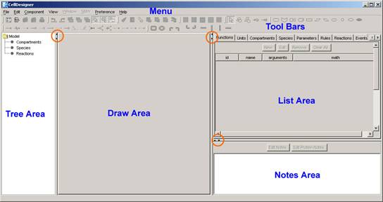
CellDesigner consists of four areas as shown above:
- Draw Area:
to draw a model. - List Area:
to display and edit the list of the components, functions ….of a model - Notes Area:
to display and edit the notes of the component - Tree Area:
Displays all the list of the components in the tree structure
Change the area size:
- The size of the area can be changed by dragging the border lines.
- To maximize the area, click the triangle icons on the borders.
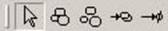
Customize Tool bar:
- Each group of the icons can be detached from the Tool Bar.
- It can also move to the left side of the screen by dragging the handle to the left boundaries.
2 Quick Tutorial of Model Building
This section is for beginners, and describes how to edit and what kind of model to be edited with CellDesigner in brief.
Take a sample file “M-Phase.xml” to open in the CellDesigner. This model contains most of the essential CellDesigner's expression of biochemical networks.
2.1 Open a File:
- Select File – Open in main menu bar to open M-Phase.xml in samples directory.
A graphical network model is displayed on the Draw Area.
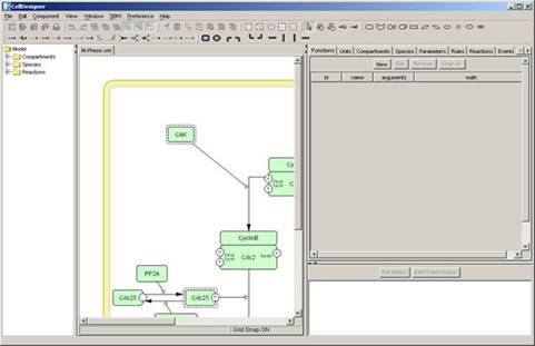
- Drag the borders (left or right) of the draw area to change the area size.

2.2 Select an Item:
- Confirm "select/move" icon is highlighted (in select/move mode).
 If not, click the icon.
 - Select shapes (not arrows, not rounding overall; called Species in SBML), and see what are highlighted.
- Select arrows (called Reaction in SBML), and see what are highlighted.
[Ans. The shapes and linked arrows.]
[Ans. The arrows and attached arrows.]
2.3 Move / Delete an Item:
 The objects highlighted in magenta are influenced by "move" and "delete" actions to the selected object.
Now,
- Drag and move the Species,
- Delete the Species and Reactions by using Backspace and / or Delete keys.
2.4 Compartment:
The other shape rounding overall is called Compartment in SBML.
- Click the Compartment (click inside without any other shapes), and see what are and how highlighted.
- Drag and move the Compartment, and confirm Species inside are on it.
[Ans. The Compartment highlighted in magenta, Species inside shadowed]
A Compartment can place Species and other Compartments inside.
2.5 Undo / Redo:
You can "undo" all of the past actions by [CTRL]-z, and then "redo" after undo by [CTRL]-y before saving the model. Try
- Undo by [CTRL]-z.
- Redo by [CTRL]-y.
2.6 Change the size of an item:
When selecting the Species and Reactions, you can see small squares appear. These are handles to change the size of Species and to bend the arrows of Reactions.
- Drag the small squares and move.
2.7 Species and Reactions:
The Species represents, for example, proteins and other molecules in biochemical networks and genes in gene regulatory networks.
The Reaction represents, for example, biochemical reactions literally, interaction between proteins, and regulatory relations between genes.
The biochemical and genetic meanings of Species and Reactions are distinguished by their symbols. The list of all symbols that can be drawn using CellDesigner and their meanings are described in [Section 6 “Symbols and Expressions].
To change the symbols of Species / Reactions:
If you double click Species and Reactions., the dialog box will appear to alter its type.
- Double click a Species (especially decorated one),
click and change anything in the dialog box, and then, see what is changed after click "Apply" button. - Double click a Species (especially decorated one),
click and change anything in the dialog box, and then, see what is changed after click "Reset" button.
2.8 Change the Shape of Compartments:
A Compartment represents a generic bounded container, such as, cell, intracellular compartment. Thus, notational change is only in visual, meaningless to semantics of biochemical and gene networks.
To change the shape of Compartment:
- Select the Compartment,
- Select Edit—Change to OVAL,
- Then select Edit—Change to SQUARE.
2.9 Activate a Species:
- Select Species and type "a" on keyboard, and see how it changes.
[Ans. The Species are wrapped by dashed line.]
The dashed line has somewhat ambiguous meanings, indicating that Species are “active” without referring their targets.
2.10 Create New Species, Reactions, and Compartment:
(*From this part, use the icons other than "select / move".)
- If you want to create new Species, Reaction, or Compartment, use icons on the tool bar.
New Species:
- Select an icon (placed in the tool bar) by click and then click a point on the canvas (draw area), where you want to place the new.

New Compartment:
- Select an icon from the compartment bar (as shown below) by click and then drag a point to another on the canvas until the new becomes suitable size.

New Reaction:
- Select an icon with an arrow on it,
 and then link Species to Species/Reaction on canvas.
(in details) Click Species on canvas you want to link by the Reaction in the order of start-point(s) to end-point(s). Reactions themselves are allowed to be endpoints of other Reactions.
There are some buttons with actions not mentioned above.
- Try the followings after select the buttons and see what happens.
- A) Create heterodimer: click several Species.
- B) Release heterodimer: click several Species.
- C) Homodimer formation: click several Species.
- D) Degradation: click several Species.
- E) Add reactant: click a Species and then a Reaction.
- F) Add product: click a Reaction and then a Species.
2.11 Add Notes to the Components:
You can add a note to any component (Species, Reaction, Compartment, and Protein).
The notes should be written in XHTML format. For details on XHTML tags and attributes, please check the XHTML 1.0 specification provided at http://www.w3.org/TR/xhtml1/
To add a note to the component:
- Select the target component (any Species, Reaction, Compartment, and Protein).
The current notes of the target component are displayed in the Notes window in the right-bottom corner of the window.
- Click [Edit Notes] button.
- Type the text you want to add as the notes to the component.
The text should be in XHTML format. - Then Click [OK] to close the dialog.
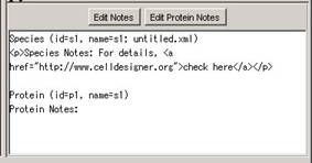 The notes you have just added will be displayed in the notes window.
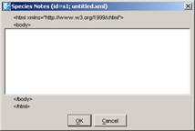 Species Notes dialog will pop-up.
Note: If the target is a protein, you can also select [Edit Protein Notes].
2.12 Export Image:
You can export the image of the model to either .PNG or .JPEG format.
- Select [File] – [Export Image…]
- Then specify the name and the file format.
The image saved here is the same as displayed on screen.
2.13 Export List to CSV file:
You can export the contents of the list into .CSV file format. This is useful when you want to check all the items specified in the model.
- Select the [Species] tab in the list window.
- Select [File] – [Export List to CSV…].
The file name is automatically specified as “M-Phase_species.csv” in the Save dialog. - Click [Save] to save the CSV file.
You may use other applications to check the contents of the CSV file.
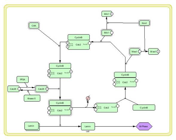
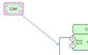
In this section, how to edit proteins with modification sites, such as "Cdc2" in the sample “M-Phase.xml”, is being described.
With CellDesigner, you can edit symbols of proteins with modification residues on a network diagram, and hence, describe detailed state transitions between Species of an identical protein with different modifications. The structure of modification residues, states, and state transitions of proteins are also stored in SBML Level 2 format with CellDesigner’s extended tags.
The model M-Phase.xml, you see, describes state transition of "Cdc2," where there are five "Cdc2"s. The five represent different Species, while essentially the same protein. Therefore, CellDesigner should handle data structure describing each protein in a model, so that several protein-type Species could have references to the same protein data. This data structure is called Protein.
3.1 Check and Change Protein Property
You can see this Protein data by selecting the Protein tab in the List Area.
If you cannot see the Protein tab, click on the right arrow in the upper right corner of the List Area, and adjust the size of the List window appropriately.
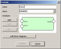
- Select "Cdc2" in the list and click Edit button.
The Protein dialog will appear. In this dialog, you can edit several properties of Protein, name, class, and residues (add, edit, and delete).
Changes in this dialog are reflected to all Species referring to this Protein.
The changes are also reflected to Heterodimers (complex of several Species) including such Species, as you expect.
3.2 Residue of Proteins
The residues of proteins can be added in the Protein dialog, but the modification of the residue status (such as phosphorylated, etc.) is NOT maintained as Protein’s property, but as Species’ identity.
- Therefore, modifications are edited by
- Double-click Species in “select/move” mode.
In the dialog appeared, you can change the modification types.
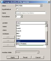
Note: You cannot add, edit, or delete modification residues in “Change Species Identity” dialog.
A Protein referred by the Species can be selected in the “Protein” pulldown in the dialog. If you want new protein, not listed in the “Protein” pulldown, select [New Protein] listed at the last and you can edit the new Protein here. Only in this case you can add, edit, and delete residues.
3.3 Block Diagram (*Proto-type)
Block diagram gives a summary view of interactions with respect to a specific Species (especially Protein) and relation between its modification and activity as enzyme. Using this block diagram editor, complex relations between Proteins can be understood at a glance and the relation between modification states enzymic activity can easily be constructed.
Note: The editor is still prototype and user interface for editing is not fully functional.
Extract Regulation:
CellDesigner extracts the interactions where the Species regulates or is regulated by other Species, from process diagram, and displays its block diagram.
- Open the dialog to check and edit Cdc2 Protein property (See. 3.1).
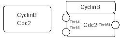
- Click “edit block diagram” button and you can see the diagram as shown below.
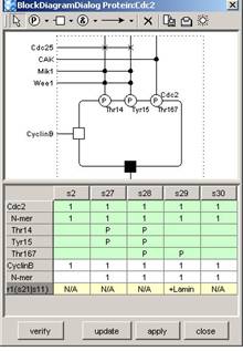
At the top side of the rectangle placed in center, states of modification residues of Cdc2 and proteins that cause change of the states (phosphorylate or dephosphorylate) are shown. At the left and bottom sides, binding to CyclinB enzymic activity to Lamina are shown respectively.
For notation details of the block diagram, see Kitano (Biosilico 1, No.5 (2003) pp.169—176) .
List in the dialog shows all the Species of Cdc2 and Complexes with other Species in process diagram (column) and their modification states and enzymic activity (row).
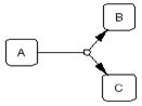
Modifications/Activations Relation:
You can edit logical relation between modification states and enzymic activity.
- Select the symbol “&” and then place them on the diagram.
- Select the arrow, then link “P”, “&”, ”□” and “■”.
[To delete a placed symbol, select the symbol and press × button in the toolbar.]
The arrows represent causal relationship and “&” , “|”, etc. are logical operators. Created logical relation can also be verified by checking consistency with contents of process diagram.
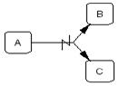
- Press “verify” button.
Enzymic activity fields inconsistent with edited logical relation are highlighted in red.
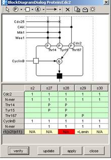
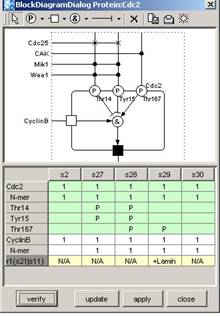
The above figures, the left is depicted by logical relation inferred by Species s29 only and the enzymic activity field of Species s28 is highlighted. The right is corrected by using the information of s28. (Note that the way of correction is not unique.)
In this section, convenient functions for editing models are introduced. CellDesigner prepares several functions that are generally seen in drawing software.
4.1 Temporal “select/move” mode
When constructing a model using buttons on toolbars to create new Species, Reactions, and Compartments (in “create new“ mode), you cannot move any components unless click the select/move icon. In model building, creating new components and layout them are likely to be repeated successively. In such case, holding “s” key on your keyboard down makes the current edit mode to “select/move” temporally. After moving some components by drag, releasing the key makes the edit mode to “create new” immediately.
Note: If you want to create components one by one, select “Input Repeat” in Edit menu to OFF the checkmark.
4.2 Cut, Copy and Paste
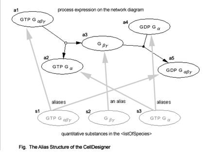
In “select/move” mode, selected Species can be cut / copied to CellDesigner’s internal clipboard by [CTRL]-x / [CTRL]-c, and pasted to the edit canvas by [CTRL]-v. The copy-and-paste action makes “real” copies of the selected Species, which are SpeciesAliases in CellDesigner’s terminology, referring the original Species. Strictly speaking, all of the Species on edit canvas are SpeciesAliases referring each original Species. By this feature, CellDesigner has multiple copies of the same Species on an edit canvas (i.e. a model), to possess ability to make various expression of a network.
4.3 Grouping
In “select/move” mode, by clicking multiple Species while holding the SHIFT key down, you can make a temporal group of the selecting Species. Moving, cutting, and copying them in a group are available. If you want the group to be permanent (saved to SBML), use [CTRL]-g while the temporary group is formed. This grouping feature is resembled to the situation, Species on a Compartment, while it has nothing to do with structure of the model. Therefore, if these two conflict each other in the canvas, “Species on a Compartment structure has priority.
4.4 Set Grid Snap ON/OFF
Snapping components on grid makes it easier to layout the pathway diagram.
Try the followings from Edit menu.
- Set Grids Size...
- Grid Snap
- Grid Visible
4.5 Zoom IN/OUT, Bird’s Eye View
You can change the zoom of the display by clicking the following icons.
![]()
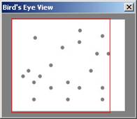
When you create a big model, it would be convenient to use the Bird’s Eye View to navigate inside the model. The Bird’s Eye View can be displayed by clicking the right most icon of the above tool bar. When you click the position you want to display in the Bird’s Eye View, you can move to the specified position.
4.6 Change Color and Shape
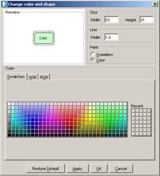 You can change the color and shape of the Species and Compartments individually or their default settings.
To change the default settings of the color and shape, select the Preference menu.
To change the color and shape of the individual components, select the components to edit, and then select the icon of Change Color & Shape ![]() in the tool bar.
in the tool bar.
4.7 Display special characters in Component name
As CellDesigner is compliant to SBML, all names of components in a model must be conforming to the SBML convention. CellDesigner 2.0 is now compliant to SBML Level 2 Version 1,1; any character that can be mapped to UTF-8 encoding can be used for the component names. If you want the special characters, such as + plus, line break, superscript and subscript, you should follow the special rules to input such characters.
Examples:::
A special character is expressed by a sequence of characters with precedent and follow up '_'s. Here are some examples:
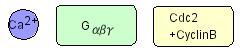 Ca2+ ("Ca" with "2+" superscript)
 - Ca_super_2_plus__endsuper_
- Ca_super_2+_endsuper_
- G alpha beta gamma ("G" with Greek "αβγ" subscripts)
- G_sub__alpha__beta__gamma__endsub_
- G_sub_αβγ_endsub_
- Complex of Cdc2 and CyclinB ("Cdc2" followed by "+CyclinB" in the new line).
- Cdc2_br__plus_CyclinB
- Cdc2_br_+CyclinB
For more details on displaying special characters, check Name Expression” at Help menu.
Caution: CellDesigner uses the "name" attributes as information to distinguish Species. Therefore, even if the rendered names look the same, the different "name" attributes, for example, "Gα" and "G_alpha_", mean different Species.
In this section, how to simulate a model is described.
CellDesigner can be used as a kind of SBML file editors for simulators. You can pass the SBML data from CellDesigner to the SBML compliant simulators via SBW. You can conduct simulation seamlessly from CellDesigner via SBW to evoke such SBML compliant simulators.
To conduct time evolving simulation, you also need to know some basics of the SBML specification. Here in this document, describes the minimum requirements for simulation.
See also:
- For more details on SBML Level 1 specification, please check http://sbml.org/specifications/sbml-level-1/version-2/sbml-level-1-v2.pdf
- For SBML Level 2, see http://sbml.org/specifications/sbml-level-2/version-1/sbml-level-2.pdf
5.1 Setup for Simulation
Before you start simulation, you need to check if the SBW and SBW-powered simulator modules have been installed in the path mentioned in Section 1.2 “Install SBW and SBW Modules”.
- To check if the SBW is properly installed, start CellDesigner and open a model. SBW menu in the main menu is enabled if your setup has correctly been done.
- Check if there are any simulators listed in the SBW menu.
If you have installed the simulators of your choice correctly, they are listed under SBW menu. The following is the SBW menu in typical environment on Windows.
Typical SBW menu
- Save Network Object Model Clipboard
- Simulation Service
- Save Model as Matlab ODE Function File
- Save Model as Matlab SimuLink Function File
- Gibson Simulator
"Simulation Service" appears if Jarnac has been installed. The others are default-installed.
5.2 Simulate a model
Try simulation with a sample file:
- Open simulation.xml in "samples" directory.
- Choose Simulation Service from SBW menu.
This wakes Jarnac up and gives the model simulation.xml to it. - Check the help or manual of the simulator to learn how to start the simulation.
5.3 Data required for Simulation
From side of SBML model building, you should specify first at least some Species and its attributes, and Reaction and its attribute for simulation. The minimum requirement of their attributes might be:
- Species: -initialAmount (default=0.0),
- Reaction: -reactant: -SpeciesReference: -stoichiometry (default=1), -product:
- -SpeciesReference: -stoichiometry (default=1), -kineticLaw: -formula -parameter,
where the rightmost of each line is required to be input.
Species Attributes
The attribute “initialAmount” should usually be changed to a positive value.
The attribute “formula” should be text string according to SBML Level 1 specification, probably including id (name in SBML Level 1) attribute of Species and parameters defined by the attribute “parameter.” These attributes can be set at the Species list shown in the List Area.
Reaction Attributes
The attributes and parameters of the Reaction can be specified at the Reaction dialog and their child dialogs.
- Open and see simulation.xml in samples directory.
- Check the Reactions list in the List Area to see how the kinetic laws and parameters are specified.
For the other parameters required, the default values specified in SBML Level 1 are used.
In this section, symbols for building models with CellDesigner are listed. Graphical notation and listing of the symbols are based on proposal by Kitano (http://www.sbw-sbml.org/workshops/sixth/sbmlsbwstockholm.htm). The symbol system for state-transition diagram and the residue state representation among the proposal are almost realized with CellDesigner.
6.1 Basic Symbols
6.1.1 Species
There are twelve types of Species symbols.
| Species | . | activated |
| protein Generic |  |
|
| protein Receptor |  |
 |
| protein Ion channel |  |
|
| protein truncated |  |
 |
| gene | ||
| RNA | ||
| Anti-sense RNA | ||
| phenotype | ||
| ion | ||
| simple molecule |
6.1.2 Modifications of Protein Residues
There are seven types of symbols for residue modification states. The residue symbols accompanied with their label (used for residue name and position in amino acid sequence) can be attached to all protein-type Species.
| Phosphorylated |  |
|
| Acetylated |  |
|
| Ubiquitinated |  |
|
| Methylated |  |
|
| Hydroxylated |
|
|
| Empty |  |
|
| Don’t Care |  |
|
| Unknown |  |
6.1.3 Compartment
There are ten types of Compartment symbols. For each type, the thick line indicates outside of its boundary.
| Square |  |
|
| Oval |  |
|
| Close-up type | Northwest, Northeast
Southwest, Southeast |
|
| Close-up type | West, East
North, South |
6.1.4 Reaction
There are thirteen types of Reaction symbols.
Reactions |
||
| State Transition |
|
|
| Known Transition Omitted |
|
Abbreviated symbol of several Reactions |
| Unknown Transition |
|
|
| Transport |
|
|
| Catalysis |
|
|
| Unknown Catalysis |
|
|
| Inhibition |
|
|
| Unknown Inhibition |
|
|
| Add Reactant |
|
|
| Add Product |
|
|
| Heterodimer Association |
|
|
| Dissociation |
|
|
| Truncation |
|
Dissociation of Proteins by truncation. |
| Transcriptional Activation |
|
|
| Transcriptional Inhibition |
|
|
| Translational Activation |
|
|
| Translational Inhibition |
|
6.2 Expressions
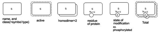
Here are symbols acquiring additional semantics by shape, combination of symbols, or change in drawings. Active t the Species is active.
Active |
|
|
Channel Open |
|
Activate Ion_Channel. |
Homodimer formed |
 |
Double-click the Species to open the identity dialog, then set the Homodimer number. |
Heterodimer formed |
|
|
Hypothetical Species |
 |
Double-click the Species to open the identity dialog, then check the hypothetical ON. |
Reversible Reactions |
Double-click the Reaction, then set “reversible” to “true” |
|
Bidirectional Reactions |
Simply draw two state transitions and reposition them |
|
Homodimer formation |
Click the icon of Homodimer formation. |
|
| Degradation of Species | Click the icon of Degradation. | |
7.1 Limitations
- (a) Available actions of UNDO and REDO are limited to actions making change on the draw canvas.
- (b) Regarding Heteromultimer:
As CellDesigner adopts the alias structure (as described Section 4.2 “Cut, Copy and Paste”), any heteromultimer created out of SpeciesAliases is regarded as a new SpeciesAlias. Therefore, the attributes specified to the individual components (SpeciesAliases) will not be maintained in the newly created heteromultimer.
Once the heteromultimer is being created, you can no longer edit the individual components of the heteromultimer. To edit the individual component, you should release the heteromultimer, and edit them, then re-create them as a new heteromultimer.
7.2 Known Issues
- (a) The problems are reported in printing / exporting images of the huge model due to the lack of the memory.
- (b) When using CellDesigner in non-English environment on MacOSX and Linux, letters on dialog boxes from File menu are not correctly displayed.
- For MacOSX, open “System Preferences” and click “International” icon from “Personal” row, and then click “Language” tab. In the window for choosing language, place “English” at the top. (Note: The terms quoted by “_“ depend on your environment.) Then start CellDesigner.
- For Linux, unset LANG in the shell, then starts CellDesigner.